P1 PROCESSOR
N5,6,7 - R5,6,7, EARLY R60,70 PRIOR TO “HAWK SERIES”

-
 First and foremost, make sure to level your concave. This is very important on Gleaner rotaries.
 -
Remove every other wire from concaves if they're closer than 1".
-
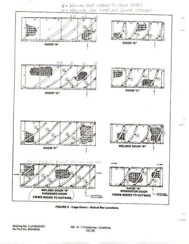
Add and double-stack helicals according to the diagram below.
P1 CAGE
-
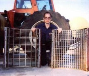
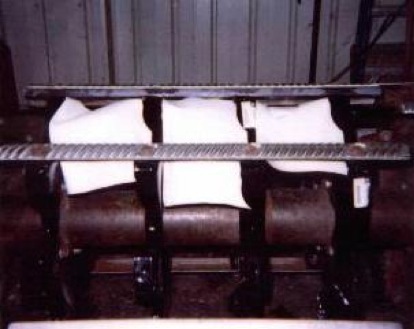
Below are pics of Hyper Harvest II's modified separator grate for P1 processors.
-
The grate in Dave's right hand is one he had specially made. It has half as many crossbars and twice as many wires. This allows green stems or stalks that come through wire area to roll over and get pulled back into the cage area. This greatly reduces shoe load and takes considerably less horsepower.
-
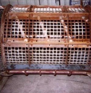
The pic to the right shows the grate being installed into the cage. This cage is approximately 150 degrees. Install 2 pieces of 1/2" by 2" flat iron for grate to bolt to. The front side butts up to existing cage door and mounting iron. The bottom cage area that is welded in will have approximately 10" of cage left after grate is installed. This grate can be installed with cage in combine. - Dave Moeller aka "Hyper Harvest II"
-
Another view of the new separator cage.
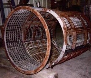
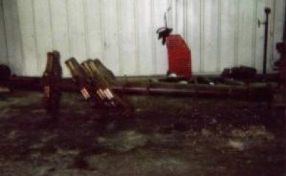
After rotor removal:
P1 ROTOR
-
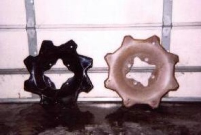
We want to achieve a "High - Low" cylinder bar configuration in the separation end of the rotor. To do this, you remove the P1 stars (as shown above) and replace them with P3 stars, which are smaller in diameter. This pic shows the difference.
-
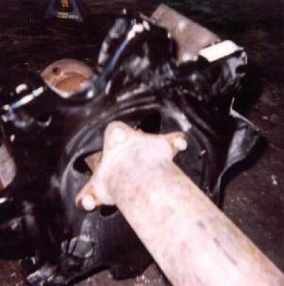
The smaller P3 stars are bolted to the OPPOSITE side of mounting ear than the original P1 stars - shown here.
-
Next, the original separator cylinder bars are reinstalled on P3 stars. Four of the separator bars are attached directly to P3 stars. Don't forget to replace reverse bars with forward bars.
-
Remove all reverse bars - throw away, melt down and make trinkets, or weld together for boat anchors
-
You'll need to remove cylinder bars from separator end of rotor.
-
Loosen and remove cylinder "stars" from center tube - pic to the right shows this step.
-
Remaining four cylinder bars are bolted to P3 stars using 3/4" by 1 1/2" flat iron as a spacer plate between star and cylinder bars. This gives you the high-low cylinder bar concept. With this arrangement, every other bar is original height (bars with spacers under them) and every other bar is a low bar. (Shown here)
-
Two more discharge paddles are added to feed impeller/chopper more evenly. Notice the two original paddles are bent due to impeller/chopper belt failure. (Right)
-
When finished, the bars in the High-Low bars do not line up with the original bars on thresher end of rotor. This does not cause a problem. (Right)
-
The "High - Low" cylinder bar concept helps relieve pressure inside cage area and also gives a tumbling effect to help separate grain from material. Distance between "high" bars and cage is now 1 1/4", and without the spacer (low bar) it is a full 2".